CAD の2つの考え方の違いが主題。OnShape はブラウザで動くクラウド CAD で、履歴を持つパラメトリック方式である。
要点はどちらが優れているかではなく、いつどちらを使うかである。
- パラメトリックとダイレクト — 履歴を持つか持たないか
- ダイレクトモデリングの基礎 — メッシュを粘土のように扱う
- OnShape でのモデリング — 作り方の順序
- 上顎歯列の模型 — 開いた殻を、台座つきの閉じた立体にする
パラメトリックとダイレクト — 履歴を持つか持たないか
| パラメトリック | ダイレクト | |
|---|---|---|
| 考え方 | 作り方の履歴(フィーチャーツリー)を保存する | 形そのものを直接押し引きする |
| 変更 | 寸法や拘束を書き換えると下流が自動で再計算 | その場で形が変わる。履歴は残らない |
| 得意 | 設計の反復・寸法が決まっている部品・部品どうしの整合 | 他所から来たデータの修正・概形の探索 |
| 苦手 | 複雑な有機的形状・履歴の破綻 | 後から寸法を変えられない |
手順(パラメトリック):スケッチ(2D)→ 拘束と寸法を与える → 押し出し・回転(3D)→ フィレット・シェルなどのフィーチャーを重ねる → アセンブリ。
医療の3D では両方が必要になる。患者データ由来の形(STL メッシュ)は数十万の三角形の集まりで、寸法という概念を持たない。だからそこはダイレクトで扱う。一方、そこに取り付けるガイドのドリル孔の直径・厚み・ネジ穴は規格で決まっているのでパラメトリックで作る。「患者の形」と「器具の規格」を1つのモデルの中で結ぶのが、手術ガイド設計の本質である。
拘束(constraint)を正しく与えることが、パラメトリックの要点である。過少拘束だと形が定まらず、過剰拘束だとエラーになる。寸法を後から変えたときに意図どおり変形するかで、設計の良し悪しが分かる(design intent)。
OnShape がクラウドである利点:インストール不要、版管理が組み込み(誰がいつ何を変えたかが残る)、同時編集ができる。医療機器の設計では設計履歴の追跡可能性が規制上要求されるので、この性質は単なる利便性ではない。
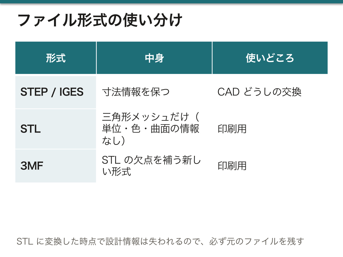
ファイル形式の使い分け:STEP/IGES=寸法情報を保った交換用、STL=三角形メッシュだけの印刷用(単位も色も曲面の情報も持たない)、3MF=STL の欠点を補う新しい形式。STL に変換した時点で設計情報は失われるので、必ず元のファイルを残す。
English version
Core
| Parametric | Direct | |
|---|---|---|
| Idea | The history of how it was made (the feature tree) is kept | The shape itself is pushed and pulled directly |
| Change | Rewrite a dimension or a constraint and everything downstream recomputes | The shape changes on the spot. No history remains |
| Good at | Iterating a design, parts with fixed dimensions, keeping parts consistent | Repairing data that came from elsewhere, exploring an outline |
| Poor at | Complex organic shapes, a history that breaks | Changing dimensions afterwards |
The sequence (parametric): sketch (2D) → give constraints and dimensions → extrude or revolve (3D) → add features such as fillets and shells → assembly.
Going further
In medical 3D both are needed. A shape derived from patient data (an STL mesh) is a collection of hundreds of thousands of triangles with no concept of a dimension, so that part is handled directly. The guide fitted onto it, however, has a drill hole diameter, a thickness and screw holes set by a standard, and those are made parametrically. Joining "the patient’s shape" and "the standard of the instrument" within one model is the essence of designing a surgical guide.
Giving the constraints correctly is the crux of the parametric method. Under-constrained, the shape is not determined; over-constrained, it errors. Whether it deforms as intended when a dimension is changed afterwards shows whether the design is good (design intent).
The advantages of OnShape being in the cloud: no installation, version control built in (who changed what and when remains recorded), simultaneous editing. In medical device design, traceability of the design history is required by regulation, so this property is not mere convenience.
Using the file formats: STEP/IGES = for exchange, preserving dimensional information; STL = triangle mesh only, for printing (no units, no colour, no information about the curved surface); 3MF = a newer format making up for the faults of STL. The moment it is converted to STL the design information is lost, so always keep the original file.
ダイレクトモデリングの基礎 — メッシュを粘土のように扱う
3Dモデルとは、実在する物や想像した物の表面を、専用のソフトで数学的に表したものである。中身は詰まっておらず、表面だけを記述している。
ダイレクトモデリングで扱う表面はメッシュで、頂点(点)・辺(点を結ぶ線)・面(辺で囲まれた三角形や四角形)からできている。面の数が多いほど曲面は滑らかに見えるが、ファイルは重くなる。形の作り方には次のような型がある。
| 作り方 | 中身 |
|---|---|
| プリミティブ | 立方体・球・円柱・円錐・トーラスなどの基本形を置く。穴あけや留め具の部品に使う |
| ボックスモデリング | 立方体から始め、面を分割・押し出しして手や頭などの形に近づける |
| スカルプト | 筆で表面を盛る・削る・ならす。粘土細工に近い |
| メッシュ編集 | スキャンや CT から来たメッシュを選んで切る・消す・閉じる・厚みを付ける |
できた形に材質や光を与えて写真のような画像を計算するのがレンダリング、力や動きを加えたときのふるまいを計算するのがシミュレーションである。どちらも計算量が多く、CPU と GPU に大きな負荷がかかる。代表的なソフトは、映像・ゲーム向けの Blender(無料)・Maya・Cinema 4D、工学向けの SolidWorks、そして医療の形の修正によく使われる無料の Meshmixer である。
なぜ医療ではメッシュ編集が中心になるのか。CT のセグメンテーションや3D スキャナから来るデータは、はじめから三角形の集まりで、寸法や作り方の履歴を持たない。これを直すには、形を直接つかんで動かす方式しかない。
細かければよいわけではない。FDM のノズル径はふつう 0.4 mm 前後なので、それより細かい三角形を作り込んでも印刷には出ない。面の数は、印刷の精度と用途に見合うところで止める。
シミュレーションは医療でも使われる。たとえば下顎の再建用プレートに有限要素解析をかけ、噛む力がどこに集中するかを色で示して、折れやすい形を術前に避ける。
English version
Core
A 3D model is a mathematical description of the surface of a real or imagined object, made in special software. It describes only the surface, not the inside.
In direct modelling the surface is a mesh of vertices (points), edges (lines between points) and faces (triangles or quads). More faces look smoother but make the file heavier. Ways to build shapes: primitives (cube, sphere, cylinder, cone, torus — used for holes and fasteners); box modelling (start from a cube, split and extrude faces into a hand or head); sculpting (add, remove and smooth with brushes, like clay); mesh editing (select, cut, delete, close and thicken meshes from scans or CT).
Rendering computes a photo-like image with materials and light; simulation computes how the shape behaves under force or motion. Both need heavy CPU/GPU work. Typical software: Blender (free), Maya and Cinema 4D for film and games, SolidWorks for engineering, and the free Meshmixer, often used to fix medical shapes.
Going further
Why is mesh editing central in medicine? Data from CT segmentation or 3D scanners are already a set of triangles, with no dimensions or design history. The only way to change them is to grab and move the shape directly.
Finer is not always better. An FDM nozzle is usually about 0.4 mm, so triangles finer than that never show in the print. Stop at a face count that fits the printer and the purpose.
In the clinic
Simulation is used in medicine too: finite element analysis of a mandibular reconstruction plate shows in colour where chewing forces concentrate, so weak shapes can be avoided before surgery.
OnShape でのモデリング — 作り方の順序
基本の練習は図面どおりの部品を OnShape でモデリングすること。寸法はミリメートルで与えられる。
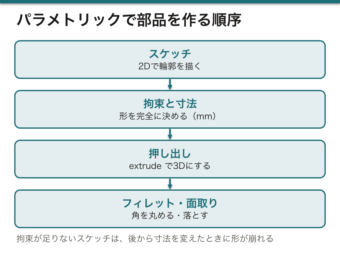
作り方の順序——スケッチを描く → 拘束(constraint)と寸法で完全に決める → 押し出し(extrude)→ フィレット・面取り。拘束が足りないスケッチは、後から寸法を変えたときに形が崩れる。パラメトリック方式の利点はここでしか出ない。
OnShape はブラウザで動くクラウド CADなので、インストールが要らず、履歴とバージョンがサーバに残る。ファイルを送らずに、共有するだけで渡せるのはこのため。
無償の教育プランは作ったドキュメントが公開扱いになるので、患者データは絶対に載せないこと。
English version
Core
The basic exercise is to model the part in a drawing in OnShape. The dimensions are given in millimetres.
The order of construction — draw the sketch → fix it completely with constraints and dimensions → extrude → fillet and chamfer. A sketch that is not fully constrained collapses when a dimension is changed afterwards. The advantage of the parametric method appears only here.
OnShape is a cloud CAD running in a browser, so no installation is needed and the history and versions remain on the server. This is why it can be handed over just by sharing, without sending a file.
Going further
On the free education plan the documents created are treated as public, so patient data must never be put there.
上顎歯列の模型 — 開いた殻を、台座つきの閉じた立体にするMaxilla
口腔内スキャナで上顎 Maxilla(上顎骨)の歯列を撮ったデータは、見えた面だけの開いた殻である。歯と歯肉の表面はあるが、縁はぎざぎざで、裏側も底も無い。これを Meshmixer で印刷できる模型にする手順は次のとおりである。
①読み込む → ②筆で縁の荒れた部分やはみ出しを塗って選び、消す(きれいな外周になるまで繰り返す)→ ③筆を小さくし、縁の線をダブルクリックして縁に沿った帯を選ぶ → ④その帯を数回広げる(歯にはかけない)→ ⑤選択の境目を滑らかにする → ⑥移動(Transform)で縁を下へ引き出し、まっすぐな台座の壁を作る → ⑦Make Solid で開いた殻を閉じた立体に作り直す → ⑧平面で切って(Plane Cut)底を平らにする。ここまでで FDM で印刷できる。
SLA(光造形)で印刷するなら、さらに準備が要る。液体の樹脂を光で固める方式なので、中まで詰めると樹脂の無駄で重い。そこで中を空洞にして壁を一定の厚さにし、未硬化の樹脂を抜く穴を開ける。造形台に対して傾けて置き、張り出した部分にサポートを付ける。印刷後はアルコールで洗い、紫外線で二次硬化させる。
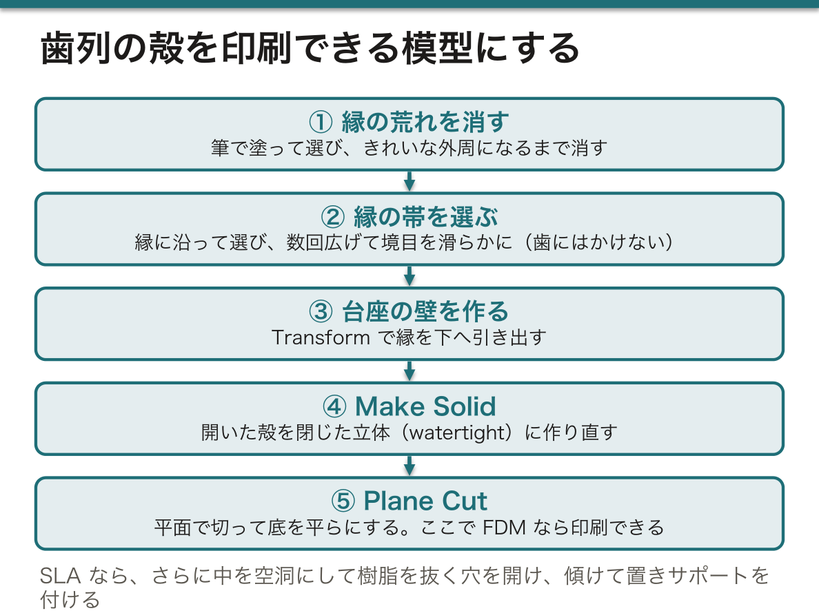
なぜ「閉じた立体(watertight)」でなければならないのか。STL は三角形の一覧にすぎず、どちらが中身かは面の向きでしか分からない。縁が開いていると内と外が決まらず、スライサは層の断面を正しく作れない。Make Solid と Plane Cut はこの「中身を決める」ための操作である。
SLA の空洞に穴が要る理由は、閉じた空洞に残った液体の樹脂が後から漏れたり、印刷中に吸盤のように働いて造形物が造形台から剥がれにくくなったりするからである。歯科模型に SLA が好まれるのは、層が薄く、咬合面の細かい形まで再現できるからである。
口腔内スキャナと3Dプリントは、アルジネート印象と石膏模型を置き換えつつある。印刷した歯列模型は、矯正用のマウスピース、歯ぎしりや顎関節症の咬合スプリント、義歯、インプラント埋入のガイドの土台に使われる。
English version
Core
An intraoral scan of the upper dental arch (Maxilla) is an open shell of only the visible surfaces: teeth and gums, with a rough rim and no back or base. Steps in Meshmixer: ① import; ② brush-select the rough rim and stray parts and delete them (repeat until the outline is clean); ③ with a small brush, double-click the rim line to select a band along the edge; ④ expand the band a few times (not onto the teeth); ⑤ smooth the selection border; ⑥ use Transform to pull the rim down into a straight base wall; ⑦ Make Solid turns the open shell into a closed solid; ⑧ Plane Cut flattens the bottom. Now it can be printed by FDM.
For SLA (resin cured by light) more is needed. A solid model wastes resin and is heavy, so hollow it to an even wall and add drain holes. Tilt it on the build plate and add supports under overhangs. After printing, wash in alcohol and post-cure with UV light.
Going further
Why must the model be watertight? STL is only a list of triangles; inside and outside are known only from face direction. With an open rim, inside and outside are undefined and the slicer cannot build correct layers. Make Solid and Plane Cut fix this.
Why drain holes in SLA? Liquid resin trapped in a closed hollow can leak later, and the hollow can act like a suction cup that makes the part stick to the plate. SLA is preferred for dental models because thin layers reproduce fine details of the biting surfaces.
In the clinic
Intraoral scanners and 3D printing are replacing alginate impressions and plaster casts. Printed dental models are used for orthodontic aligners, occlusal splints for bruxism and TMJ disorders, dentures, and as the base for implant guides.
まとめ
| パラメトリックとダイレクト — 履歴を持つか持たないか | パラメトリックダイレクト考え方作り方の履歴(フィーチャーツリー)を保存する形そのものを直接押し引きする変更寸法や拘束を書き換えると下流が自動で再計算その場で形が変わる。 |
|---|---|
| ダイレクトモデリングの基礎 — メッシュを粘土のように扱う | 3Dモデルとは、実在する物や想像した物の表面を、専用のソフトで数学的に表したものである。 |
| OnShape でのモデリング — 作り方の順序 | 基本の練習は図面どおりの部品を OnShape でモデリングすること。 |
| 上顎歯列の模型 — 開いた殻を、台座つきの閉じた立体にする | 口腔内スキャナで上顎 Maxilla(上顎骨)の歯列を撮ったデータは、見えた面だけの開いた殻である。 |
このノートは医学生が授業の内容を自分の言葉でまとめたもので、診療の判断に使うものではありません。誤りに気づいたらお知らせください。