装具は固定ではなく「動きを制御する」ものである点で、ギプスと目的が違う。
設計の前に何をさせて何をさせないかを決める。これが決まらないまま形を作ると、必ず使われない装具になる。
- 下肢装具 — 3点固定と動きの制御
- 脚のスキャンから装具を作る — Meshmixer での手順と、その理由
下肢装具 — 3点固定と動きの制御
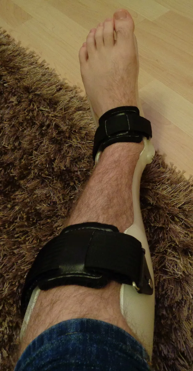
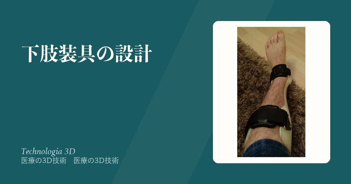
装具(orthosis)=身体の外側から力を加えて、機能を補助・制御・矯正する器具。名称は支持する関節で決まる:AFO(足関節足部装具)・KAFO(膝+)・HKAFO(股+)。
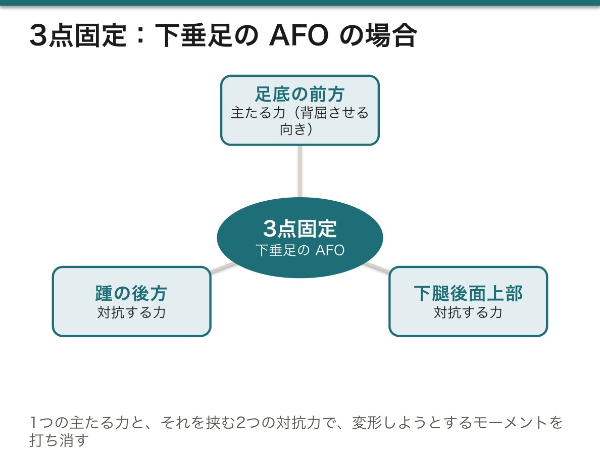
力学の基本は「3点固定(three-point pressure system)」——1つの主たる力と、それを挟む2つの対抗力で、変形しようとするモーメントを打ち消す。
代表的な適応:下垂足(腓骨神経麻痺・脳卒中)→ AFO で遊脚期の背屈を保つ、膝の不安定性 → KAFO、内反尖足の矯正、免荷。
AFO の設計は「どこまで動きを許すか」で決まる。Solid AFO(一体成型・足関節を完全に固定)は安定するが、立脚後期の蹴り出しを妨げる。Posterior leaf spring(PLS)は後方を薄くしてたわみで背屈を補助しつつ底屈を許す——3Dプリンティングが最も活きるのはこの部位ごとに厚さを変える設計である。従来の熱可塑性板では厚みを連続的に変えられない。
トリムライン(trim line)——外殻の縁の位置が剛性を決める。果部より前に来るほど硬く、後ろに下げるほど柔らかい。数ミリの違いで歩容が変わるので、ここが設計の主要なパラメータになる。
3点固定を具体的に置く。下垂足の AFO なら、①足底の前方(背屈させる向き)②下腿後面上部(対抗)③踵の後方(対抗)。力の作用点と方向を図示できることが、設計の説明責任である。
患者が使わない装具は失敗である。不使用の理由は重い・目立つ・靴に入らない・痛いの4つがほとんど。3Dプリンティングは軽量化と靴への適合、そして外観の個別化で有利になる——特に小児では、本人が気に入るかどうかが装着率を実際に左右する。
設計の検証:有限要素解析(FEA)で応力集中を確認し、実物では繰り返し荷重試験を行う。積層造形物は層間で剥離しやすいので、主応力の方向と積層方向を直交させない——印刷の向き(build orientation)が強度を決める。
English version
Core
An orthosis = a device applying force from outside the body to assist, control or correct function. It is named by the joints it supports: AFO (ankle-foot orthosis), KAFO (with the knee), HKAFO (with the hip).
The mechanical basis is the three-point pressure system — one principal force and two counter-forces flanking it, cancelling the moment that would deform the limb.
Typical indications: foot drop (peroneal palsy, stroke) → an AFO maintaining dorsiflexion in swing, instability of the knee → a KAFO, correction of equinovarus, offloading.
Going further
The design of an AFO is decided by how much movement is to be allowed. A solid AFO (one piece, the ankle completely fixed) is stable but impedes push-off in late stance. A posterior leaf spring (PLS) is thinned behind so that its flexion assists dorsiflexion while permitting plantarflexion — and it is in this design of varying the thickness region by region that 3D printing tells most. A conventional thermoplastic sheet cannot vary its thickness continuously.
The trim line — the position of the edge of the shell sets the rigidity. The further forward of the malleoli it comes the stiffer, the further back the softer. A few millimetres change the gait, so this is the principal design parameter.
Place the three points concretely. For an AFO for foot drop: ① the front of the sole (in the direction of dorsiflexion) ② the upper posterior calf (counter) ③ behind the heel (counter). Being able to draw the points of application and the directions of the forces is the accountability of the design.
An orthosis the patient does not use is a failure. The reasons for non-use are almost always four: heavy, conspicuous, will not go in a shoe, painful. 3D printing has the advantage in lightness, in fitting a shoe, and in individualising the appearance — in children especially, whether the child likes it really does decide the rate of wear.
Verification of the design: check stress concentration with finite element analysis, and carry out cyclic loading tests on the physical object. Additively manufactured parts delaminate readily between layers, so do not set the direction of principal stress perpendicular to the layers — the build orientation decides the strength.
脚のスキャンから装具を作る — Meshmixer での手順と、その理由Caput fibulae
下腿と足のスキャンデータ(STL)から足関節足部装具(AFO)の外殻を作る手順は次のとおりである。
①読み込んで移動・回転(Transform)で脚を立てる → ②平面で切って(Plane Cut)膝より上を捨てる → ③下腿下部から足を選び、なだらかな変形(Soft Transform)で足を回して足関節を直角にする → ④足底を選び、Warp でダブルクリックして支持点を置き、足底を床に合わせて平らに整える → ⑤細い筆で装具の輪郭線(トリムライン)を両側に描き、境目を滑らかにする → ⑥線の内側(下腿の後面から足底)をダブルクリックで選び、切り離す(Separate)→ ⑦ワイヤーフレーム表示で三角形を見て、多すぎれば全体を減らす(Reduce)→ ⑧縁や踵など強くしたい所だけを細かくする(Refine)→ ⑨Make Pattern(三角形の辺を棒に変える設定と、六角形の格子など)で網目状の殻にする → ⑩STL で書き出す。
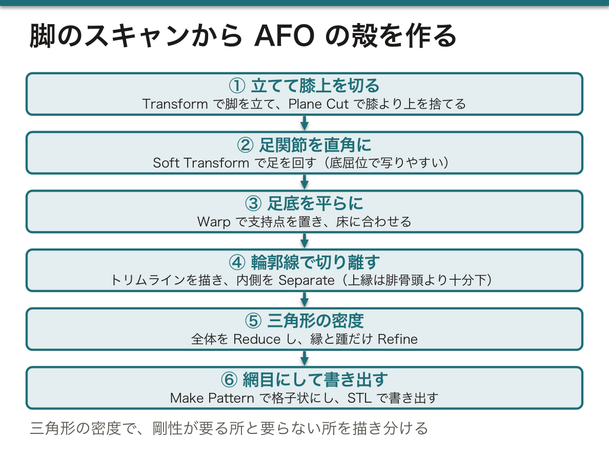
なぜ「全体を減らしてから、一部を細かくする」のか。Make Pattern は三角形の辺をそのまま棒に変える。三角形が細かすぎると棒が密集して開口ができず、重く蒸れる装具になる。そこで全体を粗くして軽さと通気を確保し、力のかかる縁と踵だけ三角形を増やして棒を密にする。剛性が要る所と要らない所を、三角形の密度で描き分けているわけである。
なぜ足関節を直角に直すのか。スキャンは力を抜いた足で撮るので、つま先が下がった底屈位で写りやすい。そのまま装具にすると、足を垂れた位置で固定してしまう。AFO は足関節を中間位(下腿と足がほぼ直角)に保つのが基本なので、形を作る前に姿勢を直す。トリムラインの位置で硬さが決まる点は、この章の最初の項目で述べたとおりである。
輪郭線を描くときは、上縁を腓骨頭 Caput fibulae(腓骨頭)より十分下に置く。腓骨頸を回る総腓骨神経は皮膚のすぐ下にあり、装具やギプスの縁で圧迫されると腓骨神経麻痺(下垂足)を起こす。下垂足を治すための装具が、作り方を誤ると同じ麻痺を起こしうるということである。外果の真上に縁や硬い棒が当たらないようにするのも同じ理由である。
English version
Core
Steps to make an AFO shell from a lower-leg and foot scan (STL): ① import and use Transform to stand the leg up; ② Plane Cut to remove everything above the knee; ③ select the lower leg and foot and use Soft Transform to rotate the foot until the ankle is at a right angle; ④ select the sole and use Warp, adding support points by double-click, to flatten it to the floor; ⑤ draw the trim line on both sides with a thin brush and smooth the border; ⑥ double-click inside the line (back of the leg to the sole) and Separate it; ⑦ show the wireframe — if there are too many triangles, Reduce them all; ⑧ Refine only where strength is needed (edges, heel); ⑨ Make Pattern (edges turned into struts, e.g. a hex grid) to make a lattice shell; ⑩ export as STL.
Going further
Why reduce everything, then refine some parts? Make Pattern turns each triangle edge into a strut. Too many small triangles give crowded struts with no openings — a heavy, sweaty brace. So the whole shell is made coarse for lightness and air, and only edges and heel get more triangles for denser struts. Triangle density draws where stiffness is needed.
Why correct the ankle to 90°? Scans are taken with a relaxed foot, which often hangs in plantar flexion. A brace made from that shape would fix the foot in a dropped position. An AFO normally keeps the ankle neutral (leg and foot near a right angle), so the posture is fixed before shaping. The trim line sets stiffness, as described in the first item of this chapter.
In the clinic
When drawing the outline, keep the top edge well below the fibular head (Caput fibulae). The common fibular nerve winds around the fibular neck just under the skin; pressure from a brace or cast edge can cause fibular nerve palsy (foot drop). A brace meant to treat foot drop can cause it if made badly. For the same reason, edges and stiff struts should not press on the lateral malleolus.
まとめ
| 下肢装具 — 3点固定と動きの制御 | 装具(orthosis)=身体の外側から力を加えて、機能を補助・制御・矯正する器具。 |
|---|---|
| 脚のスキャンから装具を作る — Meshmixer での手順と、その理由 | 下腿と足のスキャンデータ(STL)から足関節足部装具(AFO)の外殻を作る手順は次のとおりである。 |
このノートは医学生が授業の内容を自分の言葉でまとめたもので、診療の判断に使うものではありません。誤りに気づいたらお知らせください。